This article introduces that smaller components and narrower pitches pose new challenges for circuit board assembly. Understanding these placement issues can enable products to be introduced to the market faster and reduce defects.
The reality facing the industry is that parts are getting smaller and smaller. For example, 0201 chip capacitors are 75% smaller than 0402, and occupy 66% less area on the circuit board. These components will appear on some general-purpose printed circuit boards early in the decade, and even smaller 01005 chips Shaped components will be seen on module circuit boards where space is more precious by 2005.
I.C.T is a manufacturer of SMT machines. It mainly provides customers with SMT production lines including SMT Stencil Printers, Pick and place machines, Reflow Oven, AOI Machine, Wave Soldering Machine and PCB Handling Machine etc. I.C.T has more than 25 researches on SMT and DIP technology, for the world Customers provide SMT total solutions. There are successful cases of SMT technICal team in Asia, Europe, AmerICa, AfrICa, and Australia.
More details, please contact us:
Tel: +86 13670124230 (WhatsApp/Skype/WeChat)
Email: etaSMT@foxmail.com
Because the board space for many new products is so precious, although smaller components cost more, they will still be used even more widely. This new miniaturization requires improved placement accuracy without reducing speed.
Identify the challenges
Small components raise many questions. Higher density-which is the main cause of trouble with smaller components-makes the placement task an order of magnitude more difficult. For example, 0201 components usually require smaller pad sizes to prevent solder stains and to accept solderless soldering. Also, smaller pads mean narrower component pitches. Although these allow designers to achieve the higher densities required for highly functional and compact products, they also complicate the situation. For high-density PCBs, placement accuracy directly affects the number of assembly defects after reflow soldering. For example, placement offset will increase the chances of solder bridges, solder balls, component erection, and component misalignment pads.
So, what do we need? Now, the realistic production goal is to achieve a 99.9% pick-up rate, while the 3σ placement accuracy is ±60µm. In order to achieve this goal, machine accuracy becomes the primary issue.
For example, Motorola’s tests have shown that changes as small as 0.025mm in the placement offset can significantly affect the defect level. For standard pads (tested with 100,000 components), the impact of placement offset of y<0.075mm, x<0.075mm on defects is similar to that of no offset. However, when the offset increases to <0.1mm, the defect level rises to more than 5000ppm. Although this absolute distance means small, research shows that the process leaves little room for error. Also, the placement operation involves more than itself. It includes the reliability of absorption, accurate visual recognition of components and repeatability of placement. In fact, tests have shown that 0201 components require 99% absorption reliability.
Tolerance of picking position
In order to maintain the continuity of the production system, the nozzle must be able to move in all three directions, namely along the X, Y and Z axis-this is important because the Y axis control is not available on all production machines. However, in order to keep the placement accuracy within tolerance, the Y-direction control is necessary to center the component on the nozzle (Figure 1). Naturally, this alignment has tighter tolerances for 0201 than for other parts.
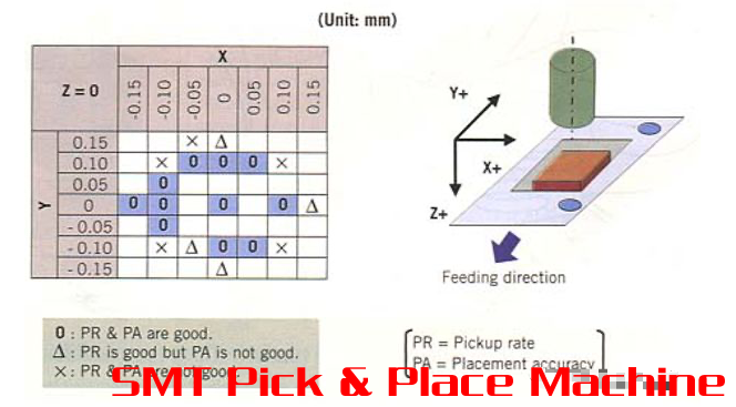
Figure 1. The Y direction is the single most important axial correction for 0201 component placement
Due to the closed loop real-time feedback on the three axes, the need for feeder calibration is virtually eliminated. Without real-time closed-loop feedback on the three axes, feeder calibration is critical.
Research has shown that the accuracy of ±0.07mm in the Y direction is necessary to ensure successful 0201 placement. Also, successful placement requires a tolerance of ±0.1mm in the X direction and ±0.1mm in the Z direction to achieve the target value of 0.2mm. Correcting the movement of the nozzle X/Y axis is the key to ensure stable and continuous component pickup.
Movement on solder paste
Another placement problem is that under certain conditions, 0201 will not stay in its placement position. Considering such a situation, the experiment will mount 0201 capacitors on a PCB printed with solder paste and flux, hoping to obtain a controlled stroke of ±0.05mm and a component spacing of 0.15mm. Experiments have shown that for the 3σ placement accuracy in the Y direction, components with an overtravel of less than 0.05mm on the board will sometimes slide more than 60μm in the short-side direction.
What will happen? Interestingly, further investigation showed that when the component is only mounted on the flux, the component will not slip due to overtravel, but it will occur when it is on the solder paste. Conclusion: The problem is the particle diameter of the solder paste. In order to compensate for the Z-axis correction, the machine must have a real-time feedback mechanism to measure the thickness of each component.
When the particle size is greater than 20µm, component skew may be possible because the particles are unevenly distributed on the pad. Because the component placement time is a few milliseconds, any uneven surface may cause the part to deflect or move. This is why the hot air solder leveling (HASL) board is not suitable for 0201 placement, which is in contrast to the 0402 approved HASL.
picture
Figure 2. When the component over-travel impacts the solder particles, the reaction force changes the axial direction of the nozzle and generates a horizontal force, which causes the component to deviate.
Therefore, overtravel reduces placement accuracy. It is also possible to increase the solder bridges for high-density placement, because when the solderless pads are used, the components will squeeze the solder paste out of the part (Figure 2). Therefore, overtravel can be defined as making the gap between the component and the PCB smaller than the size of the solder particles, that is, the placement system must control the gap to keep it at 40-60 µm. One of the contributing factors is the support of the board. Without support, components may fall from an excessively high height or be pressed into the solder paste. In order to accurately control the stroke, the support system of the board must provide sufficient correction for the arch of the board.
Improvement needed
To obtain effective use of 0201 components, part of the solution will be found in the improvement of the nozzle design. Because the components are so small, they require the nozzle design to maximize the vacuum contact surface area while providing a shape that does not interfere with the high-density layout. In addition, the suction nozzle must be highly wear-resistant, because its corrosive effect is exacerbated by the small contact area. All of these must be aware of how to meet and deal with the upcoming challenges of 01005 components.
The current result is that a gap of 0.25mm provides a tact time of 0.75, an accuracy of 60µm (3σ), and an absorption rate of 99.9%. The goal is to achieve a cycle time of 0.075 seconds per part for a gap of 0.10-0.15mm, an accuracy of 40µm (3σ), and an absorption rate of 99.9%. The tape feeder specially developed for 0201 components should also contribute to more precise and faster component placement.
in conclusion
A real economic problem is that boards produced with 0201 components will be more expensive than their corresponding larger parts. In addition, tighter tolerances necessarily require increased process control, more thorough preventive maintenance, more training and process knowledge, and increased awareness of scrap and inspection/repair activities.
Preventive maintenance is always an important part of production, and now it is even more important due to 0201 placement. Because the error tolerance and accessibility are as small as the components themselves, preventive maintenance is a more important manufacturing cost factor for the 0201 production line than other components. Similarly, it seems that the use of 0201 will require more frequent nozzle cleaning, camera cleaning, and machine placement measurements and adjustments. The height of component pickup and placement will be critical. For the initial component pickup, the feeder axis adjustment is required, although the machine can compensate for component deviation at the pickup position
Full SMT Production Line, SMT Ai Line PCB, Reflow Oven Temperature Profiler, Desktop Wave Soldering Machine, Machine Placement, SMD Placement Machine, SMT Component Placement Machine, SMT Placement Machine, Placement Machine SMT LED Placement, Chips Placement Machine, Surface Mount Placement Machine, PCB Cleaner Machine, PCB Vacuum Cleaner, Vacuum Cleaner PCB, PCB Conveyor Brush Cleaner, Robot Vacuum Cleaner PCB